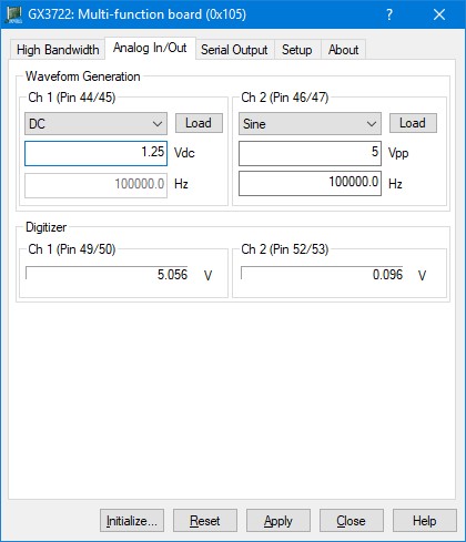
The following picture shows the Analog In/Out page settings:

GX3722 Virtual Panel – Analog In/Out page
The following controls are shown in the Analog In/Out page:
Waveform Generation group box:
Contains Arb channel controls as described below.
Ch1 – Ch2 (with pin numbers) group boxes: Specifies the channel number of the Arb output channel as well as the positive and negative output pin numbers.
Shape list: Selects the shape of the waveform to generate. Selections are: Sine, Square, Ramp Up, Ramp Down, Triangle, and DC.
Vdc / Vpp edit box: Specifies the amplitude in peak-to-peak voltage or the voltage level in Volts DC of the output waveform. VDC only applies when the selected shape is DC. VPP (Amplitude) is used for all other shapes.
Hz edit box: Specifies the frequency of the output waveform in Hertz. This control doesn’t apply when the selected shape is DC and the control will be disabled.
Digitizer group box:
Contains the Digitizer input channel controls as described below.
Ch1 – Ch2 (with pin numbers) group boxes: Specifies the channel number of the Digitizer (ADC) input channel as well as the positive and negative pin number of the differential input pair. The Text box below displays the last voltage reading taken from the ADC.