 Caution
– Do not insert or remove any board while the computer
is on. Turn off the power from the PXI chassis before installation.
Caution
– Do not insert or remove any board while the computer
is on. Turn off the power from the PXI chassis before installation.
· Install the GtDio6x driver as described in the prior section.
· Configure your PXI/PC system using PXI/PCI Explorer as described in the prior section.
· Verify that all the components listed in the packing list (see previous section in this chapter) are present.
To reduce the risk of damage to the GX5960 board, the following precautions should be observed:
· Leave the board in the anti-static bags until installation requires removal. The anti-static bag protects the board from harmful static electricity.
· Save the anti-static bag in case the board is removed from the computer in the future.
· Carefully unpack and install the board. Do not drop or handle the board roughly.
· Handle the board by the edges. Avoid contact with any components on the circuit board.
Caution
– Do not insert or remove any board while the computer
is on. Turn off the power from the PXI chassis before installation.
The GX5960 subsystem is compatible with any 6U PXI chassis that supports an air flow rate of 20 cfm/slot or greater. Power for the pin electronics requires the use of external power supplies or the GX5960 can be used with Marvin Test Solutions’ GX70005, GX7015, or GX7017 PXI chassis which is designed for the GX5960 and includes the necessary pin electronics’ power supplies. The GX5960 can also be used with the GX71xxBR-HP1 chassis which offers additional cooling and can support up to (4) GX5960 modules, for low voltage / moderate performance applications. VCC and VEE power for this configuration can be supplied via an MTS GX7400A user power supply PXI module or external power supplies.
The GX70x5 and GX7017 PXI chassis (Figure 3‑2) are designed specifically for GX5960 digital subsystems and include additional power supplies for the digital subsystems’ VCC, VEE and VDD voltages. Additionally, under software control via the GtDIO function library, the VCC and VEE voltages are programmed to the correct levels for the modules’ programmed drive / sense levels, minimizing overall module power dissipation. The GX70x5 chassis features (2) VCC programmable sources, providing additional flexibility for managing overall module power dissipation. VCC1 provides power to digital modules located in slots 4 – 11 and VCC2 provides power for slots 12 – 19, allowing the user to have two “families” of logic levels. VEE power is common to all slots, 4 – 19. Overall control / programming of the VCC and VEE power supplies is provided by a digital board (GX5961/4) which MUST be installed in slot 5. A board MUST also be installed in Slot 13 for enabling / disabling VCC2 which powers modules in slots 12 – 19.
The GX7017 accommodates the digital subsystem only in slots 13 - 20. A digital board must be installed in slot 13 to control the VCC and VEE voltages.
Caution
– When using the GX70x5 chassis, a digital board MUST
be installed in Slot 5 to control the programming of the VEE and
VCC voltages.

GX7005A Chassis
Install the board as follows:
1. Install the GtDio6x software as described in the next section.
2. Turn off the PXI chassis and unplug the power cord.
3. Locate a PXI empty slot on the PXI chassis.
4. Place the module edges into the PXI chassis rails (top and bottom).
5. Carefully slide the PXI board to the rear of the chassis, make sure that the ejector handles are pushed out (as shown in the figure below).
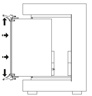
Ejector handle position during module insertion
6. After you feel resistance, push in the ejector handles as shown in the figure below to secure the module into the frame.
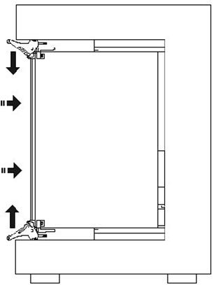
Ejector handle position after module insertion
7. Tighten the module’s front panel to the chassis to secure the module in.
8. Connect any necessary cables to the board.
9. Plug the power cord in and turn on the PX I chassis.
Plug & Play operating systems such as Windows notifies the user that a new board was found using the New Hardware Found wizard after restarting the system with the new board.
If another Marvin Test Solutions board software package was already installed, Windows will suggest using the driver information file: HW.INF. The file is located in your Program Files[ (x86)]\Marvin Test Solutions\HW folder. Click Next to confirm and follow the instructions on the screen to complete the driver installation.
If the operating system was unable to find the driver (since the GtDio6x driver was not installed prior to the board installation), you may install the GTDIO6X driver as described in the prior section, then click on the Have Disk button and browse to select the HW.INF file.
If you are unable to locate the driver click Cancel to the found New Hardware wizard and exit the New Hardware Found Wizard, install the GtDio6x driver, reboot your computer and repeat this procedure.
The Windows Device Manager (open from the System applet from the Windows Control Panel) must display the proper board name before continuing to use the board software (no Yellow warning icon shown next to device). If the device is displayed with an error you can select it and press delete and then press F5 to rescan the system again and to start the New Hardware Found wizard.
Remove the board as follows:
1. Turn off the PX I chassis and unplug the power cord.
2. Locate a PX I slot on the PX I chassis.
3. Disconnect and remove any cables/connectors connected to the board.
4. Un-tighten the module’s front panel screws to the chassis.
5. Push out the ejector handles and slide the PX I board away from the chassis.
6. Optionally – uninstall the GtDio6x driver.