
The figure below shows the available GX5964, GX5964A and GX5961 board connectors:
GX5961 Connectors
GX5961 Front Panel Connectors
The GX5961 has 7 connectors. All the connectors are available on the instrument’s front panel. The GX5961 has the following connectors:
J7 |
Power - VCC and VEE power connections for pin electronics. Not used if the GX5961 is installed in a GX70x5A/B/C chassis. |
J8 |
I/O - Programmable I/O Levels Data Connector Signals. |
J6 |
Analog I/O - 32 channel analog bus connections (connects to analog instrumentation / switch matrix). |
J10 |
High Voltage - 32 high voltage (open collector) outputs / inputs. |
J9 |
Auxiliary Channels - External connections for clocking, external events and triggering. |
BNC |
Diagnostic probe connection. |
RJ45 |
Diagnostic probe contact switch / LED connection. |
GX5694 Rev B Connectors

GX5964 Front Panel Connectors
The GX5964 has 3 connectors. All the connectors are available on the instrument’s front panel. The GX5964 has the following connectors:
J7 |
Power - VCC and VEE power connections for pin electronics. Not used if the GX5964 is installed in a Marvin Test Solution High Power chassis, e.g. GX70x5A/B/C or GX7017 chassis. |
J8 |
I/O - Programmable I/O Levels Data Connector Signals. |
J6 |
Analog I/O - 32 channel analog bus connections (connects to analog instrumentation / switch matrix). |
GX5694 Rev D Connectors
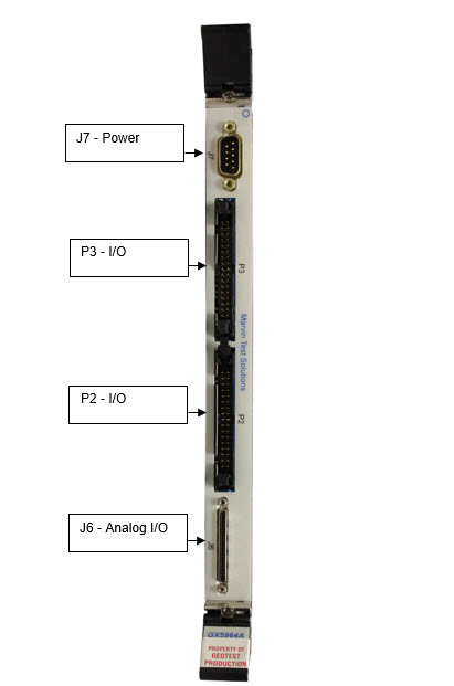
GX5964A Front Panel Connectors
The GX5964A has 4 connectors. All the connectors are available on the instrument’s front panel. The GX5964A has the following connectors:
J7 |
Power - VCC and VEE power connections for pin electronics. Not used if the GX5964A is installed in a Marvin Test Solution tHigh Power chassis, e.g. GX70x5A/B/C or GX7017 chassis. |
P3 |
I/O - Programmable I/O Levels Data Connector channels 1-16 Signals. |
P2 |
I/O - Programmable I/O Levels Data Connector channels 17-32 Signals. |
J6 |
Analog I/O - 32 channel analog bus connections (connects to analog instrumentation / switch matrix). |