Connections to the GX7400 are made using two standard D-type male connector; one for each channel.
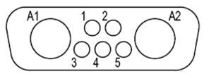
Power supply connector
Pin |
Name |
Function |
A1 |
OUT1+ |
Positive Output Power for Module 1 |
A2 |
OUT1- |
Power Return for Module 1 |
1 |
SNS1+ |
Sense for Positive Output of Module 1 |
2 |
SNS1- |
Sense for Negative Output of Module 1 |
3 |
GND |
Signal ground (reference for the Inhibit input) |
4 |
Inhibit |
Inhibit input, active low. |
5 |
SyncL0 |
For future use, do not connect |
Channel 1 Connector Pins
Pin |
Name |
Function |
A1 |
OUT1+ |
Positive Output Power for Module 2 |
|
A2 |
OUT1- |
Power Return for Module 2 |
1 |
SNS1+ |
Sense for Positive Output of Module 2 |
2 |
SNS1- |
Sense for Negative Output of Module 2 |
3 |
GND |
Signal ground (reference for the Inhibit input) |
4 |
Inhibit |
Inhibit input, active low. |
5 |
SyncL0 |
For future use, do not connect |
Channel 2 Connector Pins