IntroductionTo understand how to access registers on the GX3500 FPGA instrument, it is necessary to have a design that utilizes registers.
This document is segmented into two sections; the first provides an overview of a 128 Channel Static I/O designed for the GX3500. It is assumed that the reader is already familiar with the process of creating designs for the GX3500 using the Altera Quartus II Design tools (refer to chapter 5 of the GX3500 User’s Guide: GXFPGA Tutorial and Examples).
The design is implemented as four 32-channel bi-directional ports and is double-buffered to support simultaneous updates on all 128 channel for both writing and reading logic states.
With a functioning FPGA design, the second section of the document describes how to load the design file into the GX3500 FPGA, how to connect the GX3500 I/O ports, and how to read and write registers within the FPGA design to facilitate operation of the static digital I/O. |
|
Design Overview
Address Decoding
The Gx3500 supports two types of PCI bus read and write operations; to registers using PCI Bar 1, and to RAM using PCI BAR 2. The static digital I/O design uses registers to control writing and reading the I/O ports, so will use the PCI BAR1 chip select signal for address decoding – which is synonymous with Chip Select 1 (CS[1]). The BAR 1 signal can access a 1024 byte address range (0x400), and access must be on a 4-byte alignment (256 DWords). Figure 1 shows the address decoding logic, using five address signals (Addr[6..2]), to provide 32 write enable signals (WE[31..0]) and 32 read enable signals(RE[31..0]). These signals are used with latched registers to write to the I/O ports (WE[x]) and read from the I/O ports (RE[x]).
Figure 1: Register Address Decoding
Port Control
There are four identical I/O ports (Figure 2), one for each 32 channels. Each port supports full bi-directional capability with per-channel direction control. The output registers are double-buffered. This allows for all four ports (128 channels) to be updated simultaneously. The first stage output data is written using the WE_Data signal, and the tristate control will be written using WE_Tristate. These signals will come from the WE[31..0] signals, and are unique for each port. The second output stage is written using the WE_UpdatePort signal. This signal will also come from the WE[31..0] signals, but is common to all ports in order to facilitate the simultaneous update of the I/O ports. There is read access to the data and tristate control registers for both stages of the output registers using RE_Tristatelatch, RE_DataLatch, RE_TristatePort and RE_DataPort.
Figure 2: Port Control Logic
All channels on all four ports (128 I/O channels) are sampled simultaneously using the RE_SamplePortIO signal, and the sampled data is stored in a latched register for later retrieval using the respective port’s RE_PortIO signal. Since each port tristate control register can be read, you can deduce whether the sampled input state was generated by the GX3500 or the UUT.
Register Mapping
The following is the read and write register offsets for controlling ports A – D:
| Write Functions: | | |
|---|
| Offset | (Hex) | Function |
|---|
| 0 | (0x0) | WE[0]: Write data to Port A latch |
| 4 | (0x4) | WE[1]: Write data to Port B latch |
| 8 | (0x8) | WE[2]: Write data to Port C latch |
| 12 | (0xC) | WE[3]: Write data to Port D latch |
| 16 | (0x10) | WE[4]: Write tristate control to Port A latch |
| 20 | (0x14) | WE[5]: Write tristate control to Port B latch |
| 24 | (0x18) | WE[6]: Write tristate control to Port C latch |
| 28 | (0x1C) | WE[7]: Write tristate control to Port D latch |
| 80 | (0x50) | WE[20]: Simultaneous Update Port A – D |
| Read Functions: | | |
|---|
| Offset | (Hex) | Function |
|---|
| 0 | (0x0) | WE[0]: Read data from Port A latch |
| 4 | (0x4) | WE[1]: Read data from Port B latch |
| 8 | (0x8) | WE[2]: Read data from Port C latch |
| 12 | (0xC) | WE[3]: Read data from Port D latch |
| 16 | (0x10) | WE[4]: Read tristate control from Port A latch |
| 20 | (0x14) | WE[5]: Read tristate control from Port B latch |
| 24 | (0x18) | WE[6]: Read tristate control from Port C latch |
| 28 | (0x1C) | WE[7]: Read tristate control from Port D latch |
| 32 | (0x20) | WE[8]: Read data from Port A output |
| 36 | (0x24) | WE[9]: Read data from Port B output |
| 40 | (0x28) | WE[10]: Read data from Port C output |
| 44 | (0x2C) | WE[11]: Read data from Port D output |
| 48 | (0x30) | WE[12]: Read tristate control from Port A output |
| 52 | (0x34) | WE[13]: Read tristate control from Port B output |
| 56 | (0x38) | WE[14]: Read tristate control from Port C output |
| 60 | (0x3C) | WE[15]: Read tristate control from Port D output |
| 64 | (0x40) | WE[16]: Read sampled data from Port A input latch |
| 68 | (0x44) | WE[17]: Read sampled data from Port B input latch |
| 72 | (0x48) | WE[18]: Read sampled data from Port C input latch |
| 76 | (0x4C) | WE[19]: Read sampled data from Port D input latch |
| 80 | (0x50) | WE[20]: Simultaneous Sample Port A – D to input latch |
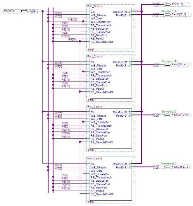
Figure 3: Read/Write Control for Ports A, B, C and D
The GX3500 Static I/O design files and the SVF file can be downloaded from  here.
here.
Software ControlTo control the GX3500 design, you simply initialize the instrument driver, load the Serial Vector File created when the FPGA design was compiled, and write and read the register locations used in the design.
The GX3500 API, distributed as a DLL, contains these and other function for accessing memory, enabling or bypassing the expansion board relays and an assortment of other miscellaneous functions. Refer to the GX3500 User’s Guide for a full list of the API functions and their calling convention.
Code for controlling the GX3500 FPGA Static IO is provided for three different programming environments; ATEasy®, “C” and LabView.
These examples assume the GX3500 is installed in slot 12 of a PXI chassis, that the SVF file produced using the Altera Quartus II design software is called “Static_IO.svf”, and that the SVF file is located in the same directory that the application program resides in. |
|
ATEasy Example (using the ATEasy GX3500 Driver)
dwData:DWord[4] ! Contains output state for 32-bit ports A- D
dwTristate:DWord[4] ! Contains tristate control for 32-bit ports A-D
dwInput:DWord[4] ! Contains data read from four latches A-D
i:Long ! Index counter
Driver Initialize (12) ! Initialize driver for instrument in slot #12
FPGA Load (".\\Static_IO.svf",TARGET_VOLATILE,MODE_SYNC) ! Load SVF file to volatile FPGA memory
FPGA Set ExpansionBoardBypass(0b1111) ! Set the expansion bypass – signals route from the FPGA to the connectors
For i=0 to 3 ! Repeat for port A - D
FPGA Write Register(i*4,4,dwData[i]) ! Write to Data Latch WE[i]
FPGA Write Register((i+4)*4,4,dwTristate[i]) ! Write to Tristate Latch WE[i+4]
Next
FPGA Write Register(80,4,0) ! Simultaneous Update all 128 I/O pins (tristate and data)
FPGA Read Register(80,4,dwData) ! Simultaneous Sample all 128 I/O pins
For i=0 to 3 ! Repeat for port A-D
FPGA Read Register(i*4,4,dwInput[i]) ! Read sampled state from Latch RE[i]
Next
“C” Example
int nHandle, nStatus, i;
DWord dwData[4], dwTristate[4], dwInput[4];
GxFpgaInitialize (12, nHandle, nStatus); \\ Initialize driver for instrument in slot #12
GxFpgaLoad (nHandle, 0, "Static_IO.svf" ,0,, pnStatus); \\ Load SVF file to volatile FPGA memory
GxFpgaSetExpansionBoardBypass (nHandle , 0xF, pnStatus); \\ Set the expansion bypass
for(i=0;i<4;i++){ \\ Repeat for port A - D
GxFpgaWriteRegister (nHandle ,i*4, dwData[i], 4, nStatus); \\ Write to Data Latch WE[i]
GxFpgaWriteRegister (nHandle ,(i+4)*4, dwTristate[i], 4, nStatus); \\ Write to Tristate Latch WE[i+4]
}
GxFpgaWriteRegister (nHandle ,80, 0, 4, nStatus); \\ Simultaneous Update all 128 I/O pins (tristate and data)
GxFpgaReadRegister (nHandle, 80, dwInput[0], 4, nStatus); \\ Simultaneous Sample all 128 I/O pins
for(i=0;i<4;i++){ \\ Repeat for port A - D
GxFpgaReadRegister (nHandle, i*4, dwInput[i], 4, nStatus); \\ Read sampled state from Latch RE[i]
}
 LabView Example
 Figure 4: LabView Example Control Panel
 Figure 5: LabView Example Frame 0 Diagram
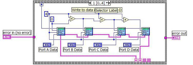 Figure 6: LabView Example Frame 1 Diagram
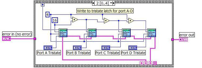 Figure 7: LabView Example Frame 2 Diagram
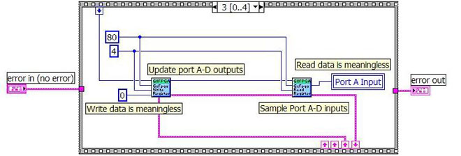 Figure 8: LabView Example Frame 3 Diagram
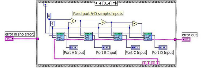 Figure 9: LabView Example Frame 4 Diagram