
The Interfaces page is used to define the interface that ATEasy is used to control and communicate with the instrument. When the Driver is initially created, no interfaces are enabled and the None interface is used.
The Interface list box displays the names of the various interfaces you can add and make available to the driver: COM, File, GPIB, ISA, USB, VXI, and Winsock. Since many instrument support more that one interface for communication, You can check off as many interfaces as you want to make available. Once the driver is inserted to your system only one interface of the checked one can be selected reflecting the way the instrument is currently connected in your system. The current interface used is selected from the Driver Shortcut Interfaces Properties page.
Note Some ATEasy drivers are implemented as None interface and are not using the ATEasy interfaces to control or communicate with the instrument, instead, they are using an external library (usually DLL). These include IVI, Function Panel drivers and LabVIEW drivers. In this case the driver is usually configured using parameters that can be entered in the Parameters Page and configured using the Misc Page.
When an interface is checked and selected, the parameters for configuring it appear to the right of the Interface table. When an interface is unchecked, the configuration parameters are grayed out.
The COM interface controls serial communication to and from devices.
● Baud Rate is the speed of transmission in bits per second. ATEasy supports baud rates from 2400 to 115200. The default baud rate is 9600.
● Handshake is the ability to control the flow of data using two hardware lines, CTS and RTS .
● Input Terminator and Output Terminator are the characters used to end lines of data. Terminators include "\r\n" (CR/LF, or carriage return plus line feed), CR, LF, "," (comma), or None (no terminator).
● Parity is a form of error correction that is used in serial communication. ATEasy can check or ignore the parity of the line data.
● Data Bits are the actual number of bits in a transmission byte. The number of data bits can range from 6 to 8, with a default of 8.
● Stop Bits indicate the end of a byte transmission. The number of stop bits may be 1, 1.5, or 2, with a default of 1.

The File interface controls reading input from and writing output of data to a file.
● File
specifies the file that will be read from or written to. You can type in the name of a new file, or choose
a pre-existing file by using the Browse ![]() button.
button.
● Mode allows you to choose among Create New (creating a new file), Create Always (creating a new file whether it exists or not), Open Existing, Open Always, and Truncate Exiting.
● Input Terminator and Output Terminator are the characters used to end lines of data. Terminators include "\r\n" (CR/LF, or carriage return plus line feed), CR, LF, "," (comma), or None (no terminator).
● Flags are the Windows file attributes that will be set for the file when it is accessed, plus some extended attributes added by ATEasy. The ATEasy-specific attributes include attributes to control buffering of input and output (Write Through, No Buffering), and attributes corresponding to the Mode pull down menu which deal with file opening and closing (Delete on Close, Open on Access.).

Note: In order to use the GPIB interface, you must have already added and configured the driver, and have the appropriate hardware board installed in your machine.
The GPIB interface controls settings for communication with instruments connected via the General Purpose Interface Bus (IEEE 488).
● Input Terminator and Output Terminator are the characters used to end lines of data. Terminators include "\r\n" (CR/LF, or carriage return plus line feed), CR, LF, "," (comma), or None (no terminator).
● When the EOI ("End Or Identify") box is selected, it means that an additional signal will be sent on that hardware line to indicate the end of transmission. The EOI check boxes must be checked in order for ATEasy to use and respond to EOI signals. The default is for these check boxes to be checked.

The ISA interface controls settings for communication with instruments connected via the ISA ("PC" ) Bus. ISA is the bus used in the original standard IBM-compatible PCs. It provides power to add-in boards and allows these boards to communicate with the motherboard. ATEasy allows direct communication with the ISA bus via various resources it makes available: DMA channels, data lines, interrupt lines, and two "windows" on memory.
● When you select Resources options settings at the Driver Interface level, you can choose from a subset of settings on the Interfaces page of Driver Shortcut Properties.
The DMA resources allow you to select what Direct Memory Access channels you will use, from 0 to 7.
The IO resources allow to specify the base address, memory increments for selecting a new base address, and top address for memory mapped devices.
The IRQ resources allow you to specify which single or multiple interrupts from 0 to 15 can be used. Do not select interrupts that conflict with other devices' interrupts. In particular, interrupt 13 is usually reserved for a math co-processor in older motherboards.
Under the Memory settings, you can select the base and top addresses of a range of memory, and the increment of a page of memory. This is especially useful when dealing with memory-mapped devices.
● The Use and Require check boxes indicate whether a particular resource will be used, and, if it is used, whether it is required.
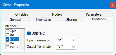
Select USBTMC for USB devices that support USB test and measurement class (USBTMC), else the device will be using the RAW mode.
● Input Terminator and Output Terminator are the characters used to end lines of data. Terminators include "\r\n" (CR/LF, or carriage return plus line feed), CR, LF, "," (comma), or None (no terminator).

Note: In order to use the VXI interface, you must have already added and configured the driver, and have the appropriate hardware board installed in your machine.
The VXI interface controls settings for communication with instruments connected via the VXI bus. VXI-based instruments may be controlled through a GPIB-controlled resource manager (slot 0), an embedded VXI computer, or a PC-based MXI interface.
● Input Terminator and Output Terminator are the characters used to end lines of data. Terminators include "\r\n" (CR/LF, or carriage return plus line feed), CR, LF, "," (comma), or None (no terminator).
● When the EOI ("End Or Identify") box is selected, it means that an additional signal will be sent on that hardware line to indicate the end of transmission. The EOI check boxes must be checked in order for ATEasy to use and respond to EOI signals. The default is for these check boxes to be checked. EOI can be set for input and output.
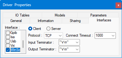
The Winsock interface allows for communication with servers and LXI instruments over TCP/IP, using either TCP, for guaranteed delivery of packets, or UDP, for connection-less non-regulated delivery.
● Client allows ATEasy to listen on the port selected and act as a client, so that two-way communication can take place with the other machine acting as the server.
● Server allows ATEasy to listen on the port selected and act as a server, so that two-way communication can take place with the other machine acting as the client.
● Protocol can be TCP, a one-to-one, connection-oriented, reliable communications service, or UDP, a connection-less datagram service that guarantees neither delivery nor correct sequencing of delivered packets.
● Connect
Timeout is the number of milliseconds until a connection times
out.
● Input Terminator and Output Terminator are the characters used to end lines of data. Terminators include "\r\n" (CR/LF, or carriage return plus line feed), CR, LF, "," (comma), or None (no terminator).