OverviewWaveEasy simplifies entry of complex analog signals by allowing the user to break the signal up into smaller, easier to define segments and sub-segments, which can easily be replicated in the pattern memory to create a complex signal.
This is especially true for signals that are of a repetitive nature, such as RS170 video. The RS170 signal will be discussed in a general sense during this article, but a full discussion of the characteristics of an RS170 signal is beyond the scope of this article, so knowledge of the RS170 signal format and timing is assumed.
It should also be noted that examples presented within this article were designed for download to the Geotest GX1110 Function Generator/Arbitrary Waveform Generator operating at 40 Ms/S (25 nS period).
For additional information about how to define waveforms in WaveEasy and load them to the GX1110 Arbitrary Waveform Generator, refer to Knowledge Base Article Q200138. | |
The RS170 standard transmits a full image at a 29.99Hz rate. The image is transmitted in an interlaced format, with one half of the image being “painted” on the screen after each vertical retrace in an alternating Even/Odd frame format. The half-frames are transmitted at ~ 60Hz rate. A typical horizontal trace signal is shown in figure 1 using common nomenclature. The Even and Odd vertical retrace signals, represented in WaveEasy, are shown in figures 2 and 3.
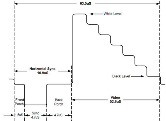 Figure 1 - RS170 Horizontal Trace Signal (Black & White) Figure 1 - RS170 Horizontal Trace Signal (Black & White)
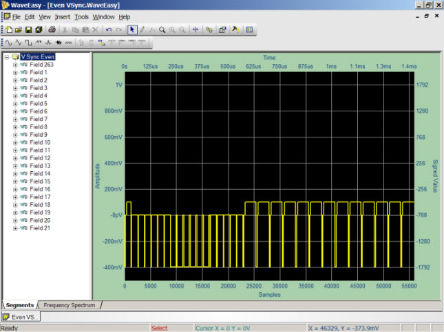 Figure 2 - Even Vertical Synchronization Figure 2 - Even Vertical Synchronization
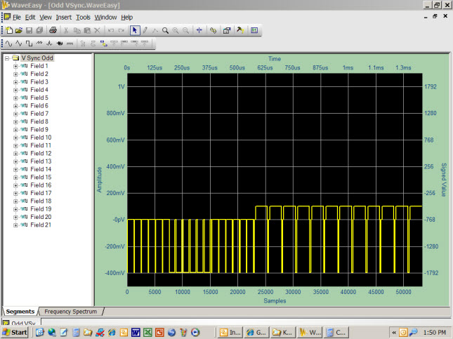 Figure 3 - Odd Vertical Synchronization Figure 3 - Odd Vertical Synchronization
Waveform Segments and Sub-SegmentsTo simplify their definition within WaveEasy, the even/odd vertical retrace synchronization signals are divided into 21 Segments (labeled "Fields"), each representing the time duration of one horizontal trace. These segments share many common characteristics that facilitate using standard copy/paste functions to build up similar, but slightly different wave components.
In between the even/odd vertical retrace signals are the 241 horizontal trace signals that represent the interlaced image. In addition, the even vertical synchronization signal has an added one-half horizontal trace field at its beginning (labeled field 263) and its end to accommodate the one-half horizontal scan line of each image frame.
The full image is composed of 21 even vertical retrace fields, plus 241 even horizontal trace fields, plus 21 odd vertical retrace fields, plus 241 odd horizontal trace fields, plus the 263rd horizontal trace tacked on to the even vertical retrace signal. This is a total of 21+241+21+241+½+½=525 horizontal scan lines – one full video frame. | |
Each of the field segments making up the vertical retrace and horizontal trace waveforms are further divided into Sub-Segments, where individual wave components of each field can be defined. Figure 3 demonstrates this concept by defining the “Front Porch” of field #263's synchronization pulse as a 0V signal for a duration of 1.5uS (60 samples at 25 nS [40 MHz] sample rate).
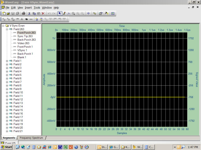 Figure 3 - Sub-Segments of Field #263 - Even Vertical Sync Waveform Figure 3 - Sub-Segments of Field #263 - Even Vertical Sync Waveform
The composite overlay of multiple WaveEasy screen captures in figure 4a illustrates how each sub-segment of field #263, as represented by a change in voltage levels, can be defined. When arranged sequentially they produce the segment pulses of Field #263 within the even vertical synchronization waveform - figure 4b.
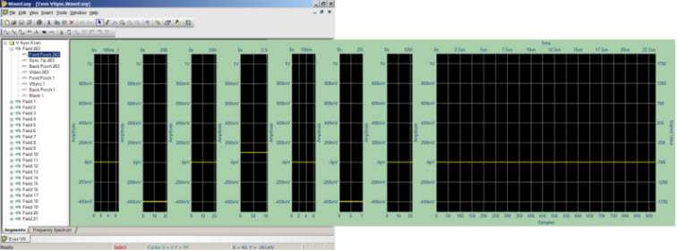 Figure 4a - Sequential Sub-Segments of Field #263 - Even Vertical Sync Waveform Figure 4a - Sequential Sub-Segments of Field #263 - Even Vertical Sync Waveform
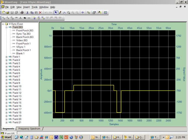 Figure 4b - Field #263 Segment - Even Vertical Sync Waveform Figure 4b - Field #263 Segment - Even Vertical Sync Waveform
The same process is used to define the remaining frames in the vertical sync waveforms. Where fields are identical to those already defined, copy and paste functions can be used to easily replicate those component waveforms. And where new pulse streams are required, sub-segments of existing fields can be copied and pasted where applicable into the new field (figure 5). The Preview Window (bottom of figure 5) displays all segments and sub-segments of the active waveform document with the hashed lines identifying the selected segment or sub-segment.
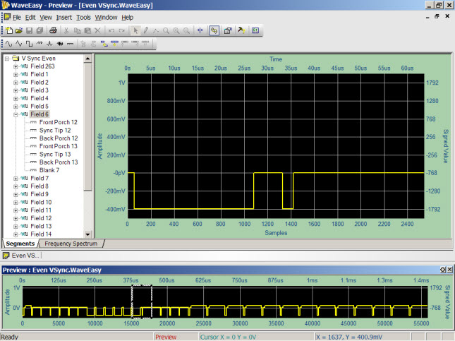 Figure 5 - Field #6 of the Even Vertical Sync Waveform Figure 5 - Field #6 of the Even Vertical Sync Waveform
Waveform FunctionsSimilar processes can be used to define the horizontal trace waveform. However, the video content – the waveform that actually defines the intensity of the image as it is painted horizontally across the screen, is defined using canned Functions built in to WaveEasy. Figure 6a shows a single horizontal trace signal consisting of a black-to-white gradient. The horizontal sync signal can be seen at the beginning of the waveform, and was created using the same process that was used to create the vertical sync waveforms. But the video content (sub-segment Video 14+) was generated using the built-in WaveEasy SawTooth function (figure 6b). The formula for defining the SawTooth waveform is:
(0.55 + 0.45 * SawTooth(1.0005 * x))
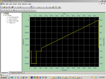 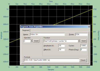 Figures 6a and 6b - Single horizontal trace signal using the SawTooth function to generate the video content Figures 6a and 6b - Single horizontal trace signal using the SawTooth function to generate the video content
If the same waveform were used for all of the 442 interlaced horizontal traces, this sawtooth waveform will generate a dark-to-white gradient across the screen from left to right. Many other simple built in WaveEasy functions can be used to create novel or useful test patterns (figures 7a and 7b).
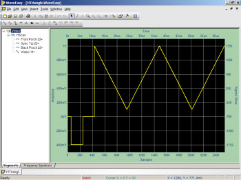 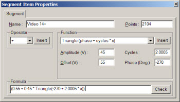 Figure 7a - Triangle Function video signal and formula Figure 7a - Triangle Function video signal and formula
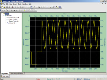 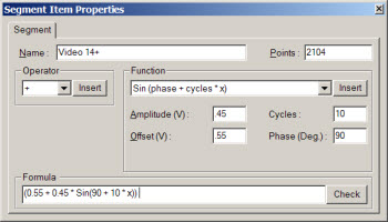 Figure 7b - Sine Function video signal and formula Figure 7b - Sine Function video signal and formula
You also have access to complex functions such as Noise (figure 8a), or combinations of functions such as Square Pulses with Sine Modulation (figure 8b). The latter will generate vertical lines across the screen of varying white intensity.
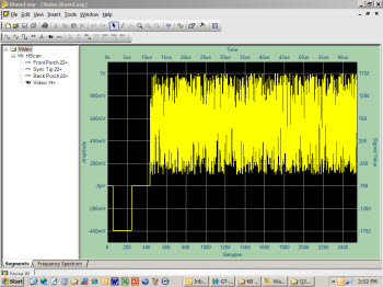 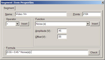 Figures 8a - Noise Function video signal and formula Figures 8a - Noise Function video signal and formula
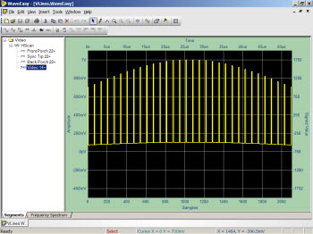 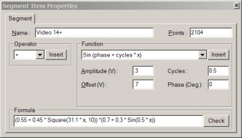 Figures 8b - Sine-Modulated Square Wave video signal and formula Figures 8b - Sine-Modulated Square Wave video signal and formula
Combining Waveform SegmentsAll of these component waveforms can be assembled to produce one full video frame. Figure 9 depicts an abbreviated video frame showing the full even/odd vertical sync pulses, each bracketing three horizontal traces (preview waveform image). Normally there would be 241 horizontal traces in between each even or odd vertical retrace. The large waveform occupying the center of the WaveEasy screen shows a magnified section of the preview waveform (hashed lines) where the signal transitions from blank horizontal traces (dark) to active video (represented by sine waves).
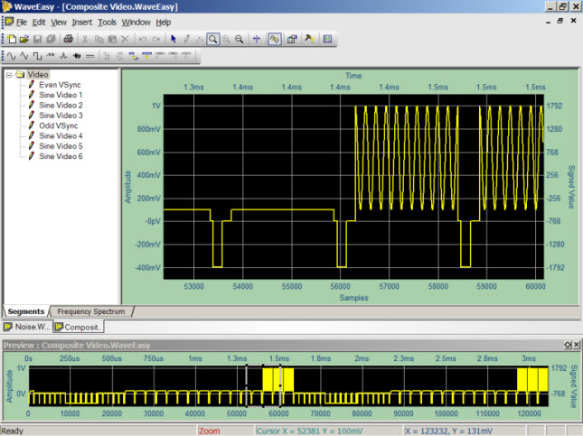 Figure 9 - Abbreviated full-interlace video frame Figure 9 - Abbreviated full-interlace video frame
The process of assembling (loading) these waveforms into a full video frame within the GX1110 is easily done via software using the supplied GX1110 driver functions. The sequence would be to load the even vertical synchronization waveform (55,880 samples), followed by 241 copies of the horizontal trace waveform (2540 samples each), followed by the odd vertical synchronization waveform (53,340 samples), followed by the remaining 241 copies of the horizontal trace waveform. The total pattern size is 1333500 samples in duration – which when output at a 40 MHz sample rate, generates a video signal with a 29.99 Hz refresh rate – exactly as defined for RS170 video. Sample ATEasy code to demonstrate this concept is provided below and sample WaveEasy pattern files can be downloaded HERE.
GTWAVE Set OperationMode ArbitraryWaveformGenerator()
GTWAVE Set OutputState(aChannelA,aOutputDisabled)
GTWAVE Stop(aChannelA)
dwStart=0
! Load fields 1 to 21 of even vertical sync, pluse field 263 for one-half horizontal traces
GTWAVE Arb Waveform FileLoad(aChannelA,"Even VSync.WaveEasy",0,dwStart,-1)
dwStart=dwStart+55880
For i=22 to 262 ! Load horizontal trace fields 22 to 262 - Completes even interlace frame
GTWAVE Arb Waveform FileLoad(aChannelA,"Sine.WaveEasy",0,dwStart,-1)
dwStart=dwStart+2540
Next
! Load fields 1 to 21 of odd vertical sync
GTWAVE Arb Waveform FileLoad(aChannelA,"Odd VSync.WaveEasy",0,dwStart,-1)
dwStart=dwStart+53340
For i=22 to 262 ! Load horizontal trace fields 22 to 262 - Completes odd interlace frame AND full video frame
GTWAVE Arb Waveform FileLoad(aChannelA,"Sine.WaveEasy",0,dwStart,-1)
dwStart=dwStart+2540
Next
GTWAVE Set Amplitude(aChannelA,1.2)
GTWAVE Set Offset(aChannelA,0)
GTWAVE Arb Set SampleRate(aChannelA,40e+06)
GTWAVE Arb Set Waveform Length(aChannelA,0,dwStart)
GTWAVE Run(aChannelA)
GTWAVE Set OutputState(aChannelA,aOutputEnabled)
|