IntroductionThe use of digital test instruments for emulating common serial bus protocols can provide benefits over dedicated bus test products and often presents a trade-off between functionality, flexibility and cost. For example, a dedicated test instrument solution can offer more extensive test capabilities such as protocol support for controlling and analyzing traffic between a bus controller and a device under test.
However, a dynamic digital solution using the GX5296 can offer the flexibility to adapt to nonstandard line rates and timing as well as supporting other digital test needs such as multi-site test capability, analog testing and the ability to test the connectivity of the Device Under Test (DUT) to the test system. Ultimately, the goal is to identify those instances where the clever or novel application of a digital test tool is appropriate and provides tangible benefits.
This paper presents an overview of how the rich feature set of the GX5296 dynamic digital I/O instrument can be used to support SPI serial bus interfaces. By using this dynamic test solution, users can potentially realize a lower cost compact test system solution with similar capabilities of the “Big Iron” test systems of the past, along with providing a common user control interface and expandability for future requirements.
| |
The Serial Peripheral Interface (SPI) bus is a synchronous serial communications interface specification used for short distance communication. Refer to the block diagram shown in Figure 1. SPI devices communicate in full duplex mode and use a master-slave configuration. Multiple slaves can be selected by using individual slave select lines. The basic SPI bus specifies four logic signals:
• SCLK : Serial Clock (output from master)
• MOSI : Master Output, Slave Input (output from master)
• MISO : Master Input, Slave Output (output from slave)
• SS : Slave Select (Active low, output from master)
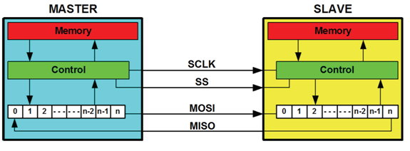 Figure 1: SPI Bus Block Diagram Figure 1: SPI Bus Block Diagram
Refer to Figure 2, the SPI bus master configures the clock polarity and clock phase with respect to the data. These are referred to as CPOL for the polarity setting and CPHA for the clock transition setting. The following example illustrates how the rich feature set of the GX5296 can be set up to test a SPI bus in any configuration. For our example the GX5296 is configured to simulate a master testing a slave in a CPOL=0 and CPHA=0 configuration.
Figure 2: Clock Polarity and Phase Timing Diagram
GX5296 Using GtDio6x SoftwareThe GX5296 is supplied with Dio6xEasy - graphical vector development / waveform display tools, GtDio6x-FIT - File Import toolkit (optional) as well as a virtual instrument panel - GtDio6x-Panel, 32 / 64-bit DLL driver libraries, and documentation. The GtDio6x virtual panel can be used to interactively control and monitor the instrument from a window that displays the instrument’s current settings and status. In addition, various interface files provide access to the instrument’s function library for programming tools and languages such as ATEasy, C/C++, Microsoft Visual Basic®, Delphi, and LabVIEW.
Our example focuses on using the GtDio6x-Panel (software virtual panel) launched from the desktop, or by selecting the program from Windows Start menu. It is recommended that most of the GX5296 setup be performed using the panel and saved to a file. This provides the simplest method to set up and or reuse test conditions.
DIO to UUT ConnectionsThe GX5296 DIO connections to the unit under test (UUT) are as follows: channel 0 is connected to the SCLK pin, channel 1 is connected to the master out (MOSI) pin, channel 2 is connected to the slave input (MISO) pin and channel 3 is connected to the slave select (SS_L) pin.
Channels SetupAs CPOL and CPHA are set to zero, SCLK is a positive edge clock and data is captured on the clock's positive transition. To achieve the positive edge clock required for this example, the SCLK channel is set to the Return To One data format. If CPOL is set to one SCLK would be a negative edge clock and therefore the channel would need to be set to the Return To Zero data format. All other channels are set to the “No Return” data format, as these pins will not need to change within the timing period.
Before beginning the instrument setup, reset the GX5296 instrument by pressing the reset button on the panel. To configure the GX5296 channels select the channels page. Refer to Figure 3 below and make the following settings. After each selection has been made, press the Apply Settings button.
- Set the Channel Mode of channels 0 thru 3 to Dynamic I/O
- Set the Channel Mode of all other channels to Disabled
- Set the Capture Mode of each active channel to Window Open Edge
- Set the Data Format of channel 0 to Return To One
- Set the Data Format of all other active channels to No Return
- Set the Phase and Window settings of channel 0 to Step TSet0
- Set the Phase and Window settings of all other active channels to Step TSet1
- Configure the Drive and Sense logic levels for each channel
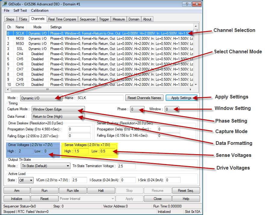
Figure 3: Configuring GX5296 Channels
System Clock SetupThe data rate used in this example is 25MHz. In order to achieve the maximum timing flexibility the T0 Clock Period should be set to the lowest practical setting and the Clocks Per Vector (CPV) multiplier set to achieve the desired timing period. For our example this means that the T0 Clock Period should be set to 10ns and the Clocks Per Vector (CPV) should be set to 4 (10 * 4 = 40ns or 25MHz). Refer to Figure 4 and set the T0 Clock Period to 10ns and the Clocks per Vector (CPV) to 4, then press the Set button. Note that the total timing period can be varied during the burst on a per step basis by changing the CPV value. The T0 Clock value is fixed for the entire burst.
Figure 4: Clock and Clocks Per Vector (CPV) Configuration
Timing SetupTo recap, we have now configured the GX5296 as follows:
- Total period timing set is to 40ns (10ns * 4)
- SCLK DIO channel is set to use Phase Step TSet0 with Return To One format
- SSL, MISO and MOSI channels are set to use Phase Step TSet1 with No Return formatting
- All Channels are set to use Window 0
In the Channel setup, each channel is assigned to one of four Phases (0-3) and four Windows (0-3). The Phases setting in the Timing Setup determines when the Drive signal will be asserted and or returned (denied) during the timing cycle. The Window setting determines when the Sensing open and close window will occur. The TSets Page is used to display the 64 Timing Set groups. Refer to timing diagram in Figure 5, SCLK transitions from a low to a high at 50% of the cycle. To achieve this clock period, Phase Assert0 must be set to 0ns and Phase Return0 to 20ns. Since data formatting for this channel is set to Return To One, this will generate the desired clock frequency as long as the vectors for this channel are set to output a low. The SS, MISO and MOSI channels are set to No Return formatting. These channels are valid at beginning of the period and remain constant during the timing cycle so Phase Assert1 is set to 0ns. Phase Return1 is not used but needs to be set to some value greater than the Phase 1 Assert, say 20ns.
To enter the Timing Set Editor, select the TSets page. Refer to figure 6, and set the Phase and Window of TSet Index 0 to the following values and then press the Write button.
• Set Phase Assert0 to 0.00
• Set Phase Return0 to 20.00
• Set Window Open0 to 30.00
• Set Window Close0 to 40.00
• Set Phase Assert1 to 0.00
• Set Phase Return1 to 20.00
• Set Window Open1 to 20.00
• Set Window Close1 to 40.00
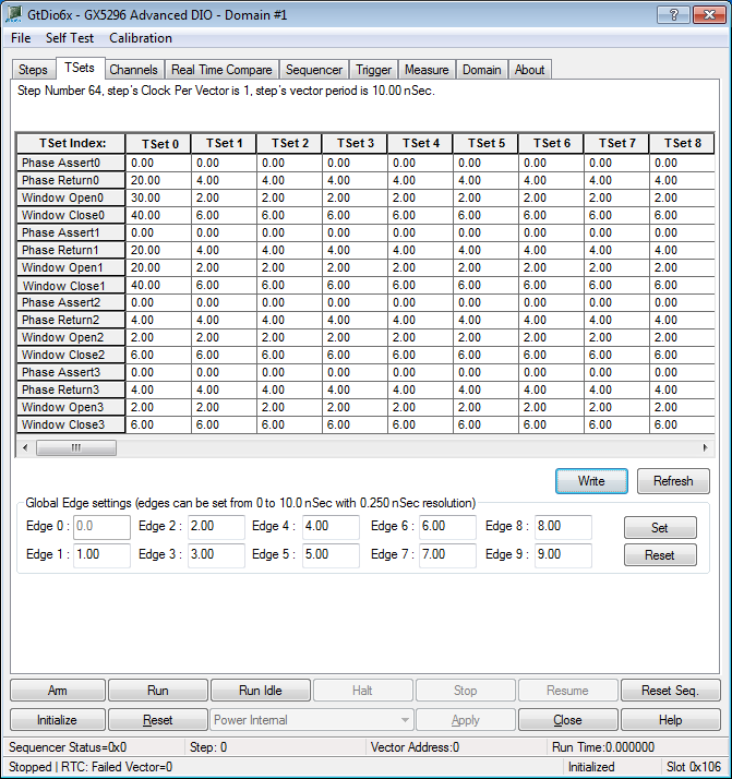
Figure 6: Timing Set Editor
Step and Vector CreationA Step is a group of vectors with a defined starting address and vector count. If desired, a Step can use the same set, a subset, or a unique set of vectors. Each vector defines the drive and sense states at the defined timing set period. Each step can select a unique CPV value, Timing Set Index (0-63), Record Memory mode, Phase Trigger Source and Step Trigger control.
Select the Steps page and refer to Figure 7. By default, the GtDio6x driver defines step 0. There are four icons used to Create, Delete, Move Up or Move Down a step. To modify the step's parameters, simply select the step by clicking on it. Our example requires two steps: Step 0 set to 50 Vectors and Step 1 set to 1 vector. Add a second step by pressing the Create New Step icon. Select Step 0 and set the Vector Count to 50 and the Address to 0, followed by the set button. Select Step 1 and set the Vector Count to 1 and the Address to 50, followed by the Set button. Our example requires that the Clocks Per Vector setting for both Step 0 and 1 be set to 4. As the CPV setting has already been set for step 0, select step 1 and change the CPV setting to 4 and press the Set button. Since our demo only uses 1 timing set group, ensure that step 0 and step 1 Timing Step Indexes are both set to zero.
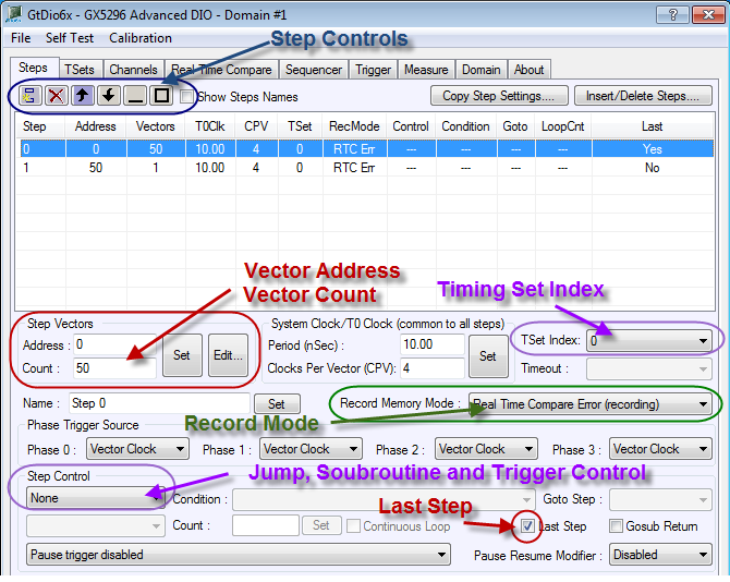
Figure 7: Step Editing
The Phase Trigger Source has two selections: “System Clock” and “Vector Clock”. The “System Clock” selection sets the selected Phase timing to the T0 Period. The “Vector Clock” selection sets the selected Phase to the System T0 Clock times the CPV setting. Note this selection can be made on a per Step basis. Refer to figure 8. If a pin is set to return to zero using a T0 setting of 8ns with 5 Clocks per vector (CPV) using “System Clock”, the pin can be set up to generate a clock of 8ns, or 125MHz. This “System Clock” pin would then generate five 8ns Clocks per 40ns timing period. Another pin using “Vector Clock” can only be set up to produce one transition per the 40ns timing period. Our example requires that both Phase 0 and Phase 1 be set to “Vector Clock”. Phase 2 and Phase 3 are not used. Perform this setting for both Step 0 and Step 1.

Figure 8: System and Vector Clock Definition
Refer to figure 9 on the Steps page, there are four record modes that are set up on a per step basis. If the vector response is known then the record mode should most likely be set to Real Time Compare Error. Using the Real Time Compare Error (Recording) mode, a burst will automatically return a pass/fail status. If however, as in our example, the application calls out to read back and analyze a response from the DUT, then the mode should be set to Response (recording). To make this selection, select each Step and select Response (recording) from the pull down menu.

Figure 9: Record Mode Selection
Any Step can be set up to perform a jump or goto subroutine. This feature can be used unconditionally or can be set up to jump, or not jump, on a specified condition. A jump can be set up to jump back to its own or any other step. There are also sixteen loop counters available to use in a jump condition. Loop counters can be nested. Our example does not require the use of Jumps or Subroutines. Ensure that the Step Control is set to “None” for both steps. The last step needs to be defined to tell the sequencer engine where to end the burst. In our Demo example, we have two steps. The first step is 50 vectors to send and receive data from the SPI bus. The second step is used as a Standby sequence step. Refer to Figure 10, at the completion of a digital sequence run the GX5296 will execute one of two Run Completion Modes - Standby or Idle. If Standby is selected the sequencer will continuously run the first vector of the indicated Run Completion Step. If Idle is selected the sequencer will continuously run the selected Idle Step. For our example, select Step 0 and make sure the “Last Step” check box is checked. Set the Sequencer Run Completion Mode to Standby and the Run Completion Step to 1.

Figure 10: Run Completion Mode Selection
Vector Editor ExampleVectors can be programmed manually or by importing a number of different simulation sources such as WGL, STIL and ATP file formats. Note that the simulation file importing requires an optional FIT licence. To edit Vectors manually select the step to edit and press the Edit button, or double click on the Step. Refer to figure 11 for an example of manual vector editing. Each channel for Vectors within the step is set to an Opcode to indicate the Drive and Sense state.
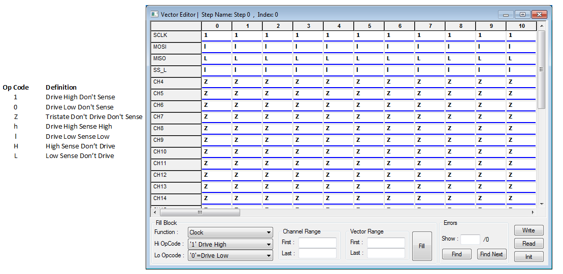
Figure 11: Manual Vector Editing
Saving the GX5296 setupA unique feature of the GtDio6x driver and panel allows all GX5296 settings to be saved into a file that can be retrieved at anytime. To save the GX5296 settings press File from the top menu and select Save. When prompted select a directory and enter a filename. Press the Okay button when finished. This greatly simplifies programming as the state of the GX5296 can be easily reprogrammed by simply loading a file from the panel, or by loading the file programmatically as in the following ATEasy example,
sFile = GetDir(aGetDirCurrent)
sFile = sFile+"\\DioFiles\\"+"SpiBusExample.dio6x"
DIO File Load(sFile,0,0,0,0)
Running the GX5296To run the GX5296, perform the following: from the panel depress the “Reset Seq.” button, select the run completion step and set it to 1, then press the “Run” button.
Reading Record MemoryRecord memory can be read by pressing the “Edit Vector” button on the Steps page of the GtDio6x panel, or can be read programmatically using the function GtDio6xReadRecordMemory. The GtDio6xReadRecordMemory function can be setup to read the results of any number of pins. In our example, the GtDio6xReadRecordMemory would be used to read the results of the MOSI line. This data can then be modified and written back to the GX5296 MISO line using the GtDio6xWriteVectorMemory function.
ConclusionWhile a dedicated test instrument can offer more targeted test capabilities for serial bus interfaces, a solution built around a dynamic digital test instrument, such as the GX5296, can offer flexibility that is unmatched when compared to a dedicated bus test tool. These features include the flexibility to adapt to multiple bus environments, adapt to changing test conditions, support nonstandard protocols (data rates, timing, message sizes…) and provide synchronization for external equipment to time-specific bus events. As the instrument also provides a full featured PMU per pin, analog and connectivity tests can also be easily integrated. A dynamic digital PXI solution can also reduce the footprint of the test system and reduce the test equipment learning curve as the test engineer is working with one instrument and learning one programming language. As can be easily seen, support for multiple serial buses with the single dynamic digital test solution can also be realized. Using a multipurpose instrument means that the test engineer needs to interface with only one vendor should technical support be required. Finally, significant cost savings can be realized since a variety of different bus protocols can be supported without incurring incremental hardware investment each time a new bus protocol is added to a test setup. Ultimately, the goal is to identify those instances where the clever or novel application of a dynamic digital test tool is appropriate and provides tangible benefits in time, cost, flexibility and effective utilization of resources. |
|
|