When interfacing to any digital logic source, it is important to provide quality signals to the device under test (DUT). And the key to providing quality signals is to treat the interconnecting cables between the digital source and the digital receiver as a transmission line requiring proper termination. This termination can take the form of impedance matching and Impedance bridging.
Impedance matching is the design practice of setting the input impedance (ZL) of an electrical load equal to the fixed output impedance (ZS) of the signal source to which it is connected, usually in order to maximize the power transfer and minimize reflections from the load1, while Impedance Bridging maximizes transfer of a voltage signal to the load2. When the output impedance of a device is connected to the input impedance of another device, it is a bridging connection if the second device does not appreciably load the previous device2. | |
For many electrical systems, simple wires and cables are adequate connection schemes, but for high-speed digital signals, this is not the case. The fast edge rates of these signals contain frequency components that are much faster that the data rate of the signals. And it is edge speed, not data rate or clock frequency that is the critical parameter. As the edge rate of the signal approaches the round-trip propagation delay of the signal through the cable, the cable begins to behave as a transmission line. A good rule-of-thumb in determining the propagation delay of a cable is to use 1nS per foot cable length. In figure 1, if the cable length (L) were 1 foot, then a digital signal with a 2nS edge rate would require that the cable be terminated with a load of Z ohms.
 Figure 1 – Unterminated Transmission Line Figure 1 – Unterminated Transmission Line
There are many methods for terminating a transmission line. While some use active components, like diodes, this article will focus on the more common method of using resistors. For instance, a common TTL transmission environment is 100 ohms. Impedances of 50-75 ohms are also used, but have a disadvantage that the termination resistors would place a large load on the digital driver. This is best to avoid, especially for "weak" drive devices. The simplest way to terminate a 100 ohm transmission line would be to place a resistor at the end or the cable (Figure 2) where RL is equal to Z Ohms.
 Figure 2 – Terminated Transmission Line Figure 2 – Terminated Transmission Line
This termination scheme, while simple, places an added load on the driver. In keeping with the above example, if the drive voltage were 5V, and RL is 100 ohms, then the termination load is 5Volts/100Ohms=50mA. This is beyond what many TTL devices can accommodate. One way to address this loading is to use a higher impedance cable. Simply changing your transmission environment to 125 ohms would lower the termination loading to 40mA – still high, but lower than the previous example. An advantage of this method of termination is the ability to handle multiple fanouts. Each fanout stub would have their own termination resistors, but the fanout network would multiply the termination loading.
To address the loading drawback, parallel termination can be used. Terminating the transmission line requires that the termination load be referenced to a power plane. While the ground plane is typically considered the termination reference, the VCC power plane can also be used (Figure 3). The resistors RPU (Pull-Up) and RPD (Pull-Down), while technically not in parallel, for the purposes of transmission line termination, are in parallel with each other. The resulting termination value is calculated using Ohms Law: RL=(RPU x RPD) / (RPU + RPD). If Z were 125 ohms, then using RPU and RPD with values of 180 ohms and 390 ohms, respectively, would result in a Thévenin equivalent termination of 123 ohms. The load on the driver, when outputting a 4V logic “1”, would only be around 10mA – well within the range of most TTL devices.
 Figure 3 – Parallel Terminated Transmission Line Figure 3 – Parallel Terminated Transmission Line
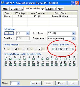
The GX5292 has 330/390 parallel termination built in and are user selectable in groups of eight channels using on-board relays. This termination is intended to provide proper termination of UUT driven signals, but has minimal affect of signals driver by the GX5292. The termination can be enabled programatically, or using the Group Termination controls on the DioEasy Panel's I/O Channel Settings tab. The GX5055 and GX5960 also provide on-board termination, however, they are controlled per pin, and includes the ability to source and sink current.
 Figure 4 – DioEasy Panel - Group Termination Controls Figure 4 – DioEasy Panel - Group Termination Controls
A little overshoot is not harmful to your system. In fact, many designs under-terminate a signal on purpose to achieve some overshoot and undershoot. This guarantees a clean transition through the UUT input thresholds so you don't linger in the hysteresis range of the receiver. It will also reduce termination loading further. Under-termination produces some ringing in the signal at the receiver (figure 4), but so long as the negative "bounce" does not drop below the input-high threshold of your receiver (Vih), there is no negative affect. As a general rule, if the ringing is not affecting your UUT's operation, then it may not be a problem and you can ignore it. A 220/330 ohm termination network would provide 132 ohm termination; slightly under-terminating a 125 ohm transmission line and producing minor ringing on the signal.
 Figure 5 – Minor ringing in a digital signal Figure 5 – Minor ringing in a digital signal
Digital signal are often part of a bi-directional bus, and it is typically a requirement that when a bi-directional line is tristated, the bus will “float” to a known level. A 125 ohm termination resistor to ground or VCC will guarantee that a tristated bus would be pulled to ground or to VCC, respectively. Parallel termination can allow a bus that is in an undriven state to float to a predetermined value. For example, 180/390 ohm parallel termination will force a tristated signal to about 46% of VCC, or about 2.3V for VCC equal to 5V.
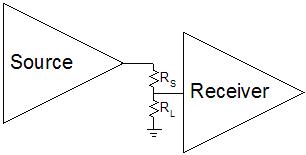
Source termination is an example of Impedance Bridging termination. As mentioned previously, impedance bridging maximizes transfer of a voltage signal to the load. Since most IC’s have a very high input impedance, large drive currents are not required to transmit a signal, so long as the voltage levels comply with the VIL and VIH parameters. Source termination places a resistor in series with the driver, with the source resistance value (RS) equal to the characteristic impedance of the transmission line (Figure 5). The resistor (RS Ohms), in series with the transmission line (Z Ohms) will appear as a voltage divider. When RS Ohms equals Z Ohms, the instantaneous voltage on the transmission line will be 50% of the voltage provided by the driver.
 Figure 6 – Impedance Bridging Source Termination Figure 6 – Impedance Bridging Source Termination
The 50% amplitude wave propagates down the transmission line until it sees the large mismatch at the unterminated receiver. Source termination relies on the large mismatch to reflect 100% (ideally) of the signal back into the transmission line – in effect, instantly doubling the voltage at the receiver from 50% of the drive voltage to 100%. Since there is very little power transferred to the receiver - remember, source termination is impedance bridging, not impedance matching, the voltage level remains nearly equal to the drive voltage. The reflected wave propagates back down the transmission line, where the source termination resistor absorbs it.
There are a couple of caveats to using this termination scheme. First, if you were to look at the signal on the transmission line side of the source termination resistor, you would see a very poor digital signal. The signal would rise to 50% of the driver voltage, remain at this level for 2x the propagation delay of the cable (approximately 1nS/ft), and then complete the transition to 100% of the drive voltage, producing a stair-step transition. However, we are not concerned with the signal integrity at the source. The receiver sees a clean 100% signal transition, which is what is important in digital signal transmission.
The other disadvantage of source termination is that it works best for a single receiver. Additional receivers on the bus will be unterminated stubs. When the source terminated signal reaches a stub, the 50% amplitude signal is divided in half again, producing a 25% amplitude signal (assuming the stub matches the impedance of the transmission line). Now the 100% reflection at the receiver produces a 50% amplitude transition (assuming a single stub), and the reflected wave when it reaches the transmission line will be split between propagating back down the transmission line, and propagating to the other stub. With multiple receivers on a source terminated transmission line, instead of seeing clean transitions at the receiver, you get a transition with steps and added ringing caused by multiple reflections bouncing every which-way. If the length of all of the stubs is very short, then the perturbations in the edge transitions will be minimal, and the signal quality might be adequate. But with source termination, as the unterminated stub lengths increase, edge transition quality for all receivers decreases.
One final caution about using source termination. Providing both source and load termination on the same signal, while resulting in a very reliable signal, will also limit the amplitude to half of what it would otherwise be. As illustrated in figure 6, double termination creates a voltage divider at the receiver. The current across RS and RL is equal, and assuming the values of RS and RL are equal, the voltage at the receiver is 50% of the source voltage, rather than the full source voltage.
  Figure 7 – Double Terminated Signal Figure 7 – Double Terminated Signal
The voltage drop from double termination can be compensated for if the source driver has programmable outputs with a range at least double the desired logic level. The GX528x and GX529x series digital instruments available from Geotest (except the GX5295) all have programmable output levels in the range of 0V to 3.6V. The GX5295 has a programmable range of -2V to +7V and the GX5055 and GX5960 have programmable output levels in the range of –10V to +15V.
Terminating a Differential transmission line requires placing a resistor of the same value as the characteristic impedance of the cable, across the differential signals (figure 8). The termination can be on either or both ends of the transmission line, depending on the application requirements. Cables are generally rated for their characteristic impedance based on the type of cable. For example, the GT95022 cable supplied with Geotest DIO instruments is a SCSI Fast cable, and as SCSI is a differential transmission standard, the cable impedance is specified as a differential Impedance of 124 ohms, ± 10 Ohms. When used in a single-ended application, then the impedance is half the rated differential impedance. |
|
 Figure 8 – Differential Termination Figure 8 – Differential Termination
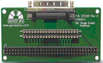
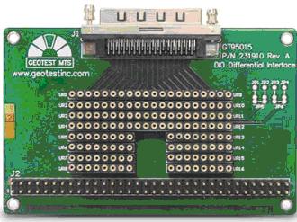
To facilitate easy connection of Geotest dynamic digital instruments, Geotest has optional breakout adapters, the GT95014 and GT95015, which provide 34 x 2 rows of male pins on a 0.1” spacing. This is compatible with a 68-pin IDC type connector. These adapters accommodate single-ended or differential signals, respectively, and provide sockets for termination resistors on the board. Documentation for these adapters can be found here ( GT95014**) and here ( GT95014**) and here ( GT95015). GT95015).
  Figure 9 - GT95014 & GT95015 Breakout Adapters Figure 9 - GT95014 & GT95015 Breakout Adapters
In summary, to guarantee good signal quality in a digital environment, it is important to understand when termination is required (as the edge speed of the signal transition approaches the round-trip delay time of the signal through the interface cable), the different methods of terminating a transmission line (source termination, single load termination and parallel load termination), and the advantages and disadvantages of each.
1. Wikipedia - http://en.wikipedia.org/wiki/Impedance_matching
2. Wikipedia - http://en.wikipedia.org/wiki/Impedance_bridging
|